Introduction
I am a PC enthusiast and enjoy putting together computers, modding them, and subsequently writing about it. I am also the tinkering owner of two PowerColor PCS+ R9 290 video cards that I have used now for over a year. This is the story of how I worked to break through the overclocking ceiling that was being limited by the stock BIOS.
I picked the PowerColor PCS+ R9 290 cards as my purchase choice because they are amazing workhorses. They are factory overclocked at 1040/1350 MHz core and memory and are competitively priced compared to other manufacturers. They are also differentiated from reference R9 290s cards due to the additional 50 millivolts of voltage that has been added to their core voltage and a heavy cooler which make them great overclockers. I have been able to overclock the pair of cards to 1120/1450 MHz core and memory until one of the cards died and I had to send it in for RMA.
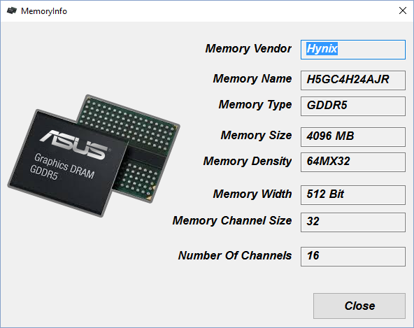
My journey into BIOS modding started here. After a few weeks of waiting I received a PCS+ R9 290 model in the mail that came with Samsung memory. This was somewhat problematic since my other card had Hynix memory but I considered myself lucky because Samsung is well known by the overclocking community to be the best manufacturer of GDDR5 memory. Their memory is able to perform at a tighter set of timings and overclock at a higher frequency compared to what other manufacturers’ products are capable of (and therefore should be superior to my other card with Hynix memory).
I happily plugged the card in and got straight to overclocking where I was horrified to find that I could never push the card past 1150/1375. The Samsung RAM refused to overclock beyond that! There had to be a way to get this card to overclock more and I was dead set to figure out how through research.
Analyzing the PowerColor PCS+ PCB
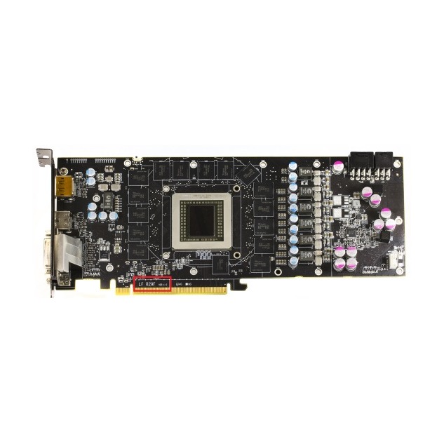
I knew that I had two PCS+ cards that should overclock similarly given what I knew about Hynix and Samsung RAM. Looking at the physical cards, the PowerColor PCS+ R9 290 series seemed to manufactured on the same non-reference PCB. The PCB revision used in the PCS+ R9 290 series is on the card as shown within the red rectangle in the image above. My two R9 290 cards came with the
LF R29F V1.0
revision and are therefore pretty much identical.
If the cards have an identical wiring layout that means that the problem was elsewhere. The handicapped Samsung card should perform better or the same given that it had the same PCB. As such, I started looking at other areas and discovered that there was another difference in the BIOS used within the software of each card. I used GPU-Z to view the BIOS and noticed the following versions:
- Hynix w/ BIOS version 015.044.000.002.000000
- Samsung w/ BIOS version
015.048.000.032.000000
I figured that perhaps my Samsung’s card BIOS had a bug. If I could find an alternative/newer BIOS perhaps that would fix the issue. I visited the Techpulse VGA BIOS Collection and started looking for a replacement BIOS. Unfortunately, none of the BIOSes in the collection supported Samsung memory and a reckless test flash with the wrong memory type quickly resulted in failed BOOT verifying that I had no luck. I flashed back to the original BIOS and begrudgingly left my clocks at stock while I worked on other side projects.
The Hawaii modding scene takes off!
A few months later the R9 390 series was released which gave the overclocking community a new window in comparing the 290 series with the 390 series. The 390 series was a re-brand of the same Hawaii GPU used in the R9 290 series which also used a fundamentally identical BIOS with minor changes (RAM size, clock speed, version, etc). The overclocking community coupled this information with other ground breaking discoveries to start the 290 series to 390 series BIOS modding scene renaissance where they started to provide 390 series BIOSes that were designed for the 290 series.
I played around with these BIOS mods and noticed that they were usually designed for reference PCBs.I did some testing and was upset to find that these BIOSes were not stable on my cards. All BIOSes are designed for a particular PCB and PowerColor’s PCB had diverged away enough from the reference design that I couldn’t use it. I would need to find a BIOS that was for my PCB.
I looked for a PowerColor R9 390 series BIOS, hoping that it shared my PCB, and found a set of the stock PCS+ 390 BIOSes:
- 390 w/ BIOS version
015.049.000.000.000000
- 390X w/ BIOS version 015.049.000.004.000000
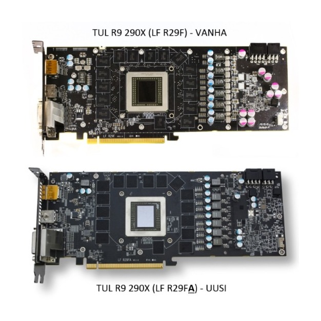
Now I had to verify now that these PCS+ R9 390 cards used the same PCB. I wasn’t about to go out and buy a card just to verify this so I used a search engine to find a “PowerColor R9 390 PCB” images and discovered that PowerColor had slightly revised their PCBs when moving from the 290 to the 390 series. The 290 PCB revision was LF R29F V1.0 and was now the LF R29FA V1.0 revision in the 390 series.
This sparked some research which revealed that PowerColor had “cheaped down PCB“ and altered the voltage regulation system on the PCB. However, the PCBs still used the same IR 3567 voltage controller so it could be similar enough to work in most regards. If the PCBs were so similar between the 290 and 390 series then perhaps the newer BIOS on the 390 series might include a bug fix for my Samsung card.
I now wanted to mod a PCS+ 390 BIOS to make compatible with my PCS+ 290 cards.
Comparing the 290 and 390 series
The R9 390 series are fundamentally identical to the R9 290 series with the exception of their:
- Memory timings (More straps vs Less straps)
- Physical memory (8GB vs 4GB)
- Clock speed (1010/1500 vs 1040/1350)
- Base voltage (900mV vs 993mV)
- ASIC Quality (Refined vs Older)
- Voltage regulation (Determined by PCB)
Of these changes the only thing that is physically different is the amount of physical memory and ASIC quality. Everything else is dictated in software by the BIOS which means most of these enhancements can be programmed or transferred.
The memory timings improvement was generally accepted as a refinement in the BIOS to support more straps. Straps are essentially a range of MHz where certain memory timings are used to keep the memory stable at that clock speed. Memory timings are also specific to a particular memory manufacturer so I would need to select the right memory timings for Samsung or Hynix.
The physical memory amount is just a function of the density of the RAM chips. There are always exactly 32 GDDR5 RAM chips on a Hawaii GPU. The 290 series simply has half the density compared to the 390 series and as such each chip has 64MB as opposed to 128MB. If I wanted to mod the BIOS I would therefore need to reduce the density.
Clock speed and base voltage are related to the ASIC quality. ASIC quality is a measure of how refined the GPU manufacturing process was and how much leakage the transistors provide. Generally there shouldn’t be too much of a difference but AMD has been tweaking/improving the manufacturing process so there should be less leaking in a R9 390 than an early release R9 290. This improvement in ASIC quality is most likely why the R9 390 series has such a lower base voltage than that of the R9 290 series. I would most likely need to still use the original voltage.
Voltage regulation is determined by the voltage controller and also VRMs on the PCB. This would continue to be one of the huge unknowns in the entire project given that the LF RF29A PCB was altered for the worse. The only way to safely play around with the voltage regulation would be copying sections of BIOSes that manage this into the PCS+ 390 BIOS.
Knowing all of this, I should be able to take a R9 390 series BIOS and adjust the memory timings, density, clock speed, and voltage to match that of a R9 290 series and keep it stable.
Modding the BIOS
Armed with a hex editor, forum documentation, and a ton of other tools of Hawaii BIOS modding I got to work. I used Atomdis, HxD, HD7xxx Series UEFI Patch Tool, and HawaiiReader (all found here) to mod the PCS R9 390 base BIOS with all the changes that I needed to do. I also referenced a set of modded 390X BIOS for 290 series BIOSes that can be found here.
After a lot of trail and error, I found that I only needed to perform the following mods:
- 4GB memory mod
- Enhanced memory timings for each strap and memory type
- Replace the PCS+ 390/390X PowerPlay with a reference 390/390X PowerPlay to stabilize voltage regulation
I ended up creating the following BIOS combinations:
Stock with a Performance Boost:
- 290 BIOS with 390 Memory Controller
- 290X BIOS with 390 Memory Controller
390X with 290X Temperatures/Overclocking:
- 390 BIOS with 290 Power Play
- 390X BIOS with 290X Power Play
390X with Low Voltage/Temperatures/Reduced Overclocking:
- 390 BIOS with 390 Power Play
- 390X BIOS with 390X Power Play
Benchmarks
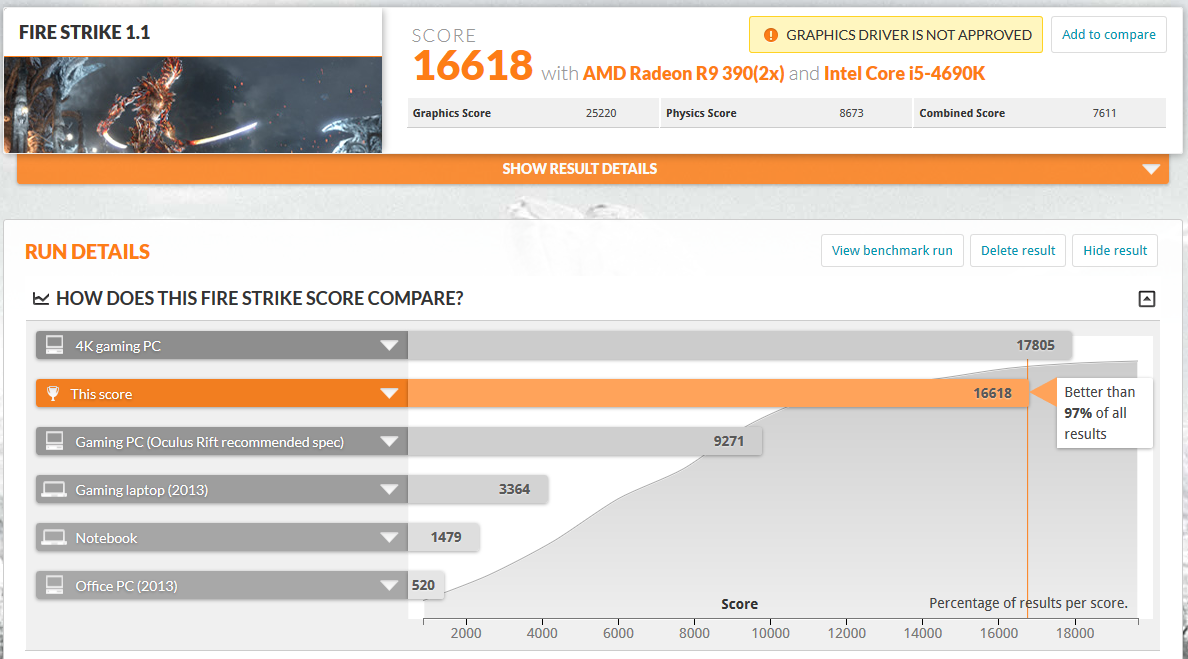
The end result of my BIOS mod is that I am finally able to overclock my Samsung card’s memory beyond 1375 MHz. In fact, I am able to reach 1540 MHz RAM using both my Samsung and Hynix cards thereby managing to eek out an additional 6% of performance according to 3dMark.
I also ended up playing around with a 290/290X BIOS and discovered that simply replacing the memory controller in the BIOS with a 390 memory controller I got a free 3% performance boost.
11/22/2016: I have noticed that the other 390 BIOSes are not stable on my machines. I have decided to just use a 290 BIOS with the 390MC but will leave this post present for anyone who wants to continue to hack.
Flashing to a modded R9 390 BIOS
For those who are adventurous and want to experiment, you can follow these steps:
- Verify that you own a LF R29F V1.0 PCB revision PowerColor R9 290/290X with 4GB of memory
- Read this thread for more detailed flashing directions
- Download my modded BIOSes here
- Backup your current BIOS
- Uninstall your drivers and delete your Afterburner/Trixx profiles.
- Flash your video card
- Reinstall the latest drivers
- Play some games to test stability
Good luck!
Disclaimer: I am not responsible for any damage caused to your device. Always keep a backup of your original BIOS.